


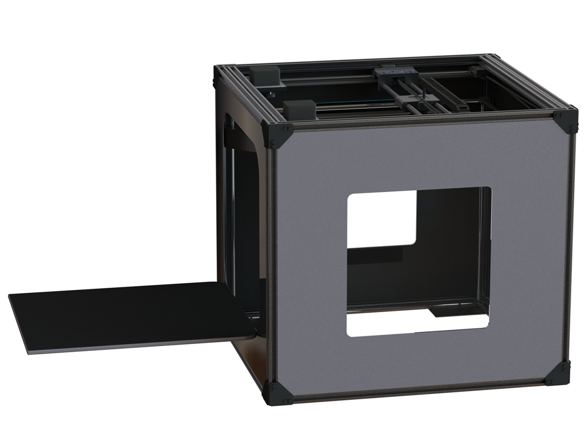
Hinged door allows easy print removal access. Plexiglass windows allow operator to supervise use.


Early designs showing concept and mechanical layout


Heat sink was sized and calculated using engineering heat transfer analysis, removing up to 12W peak output from the motors of heat energy. Fins are aluminum machined on a desktop Roland CNC machine. Belts were upgraded after this point, and pulleys had teeth added for reduced slip.

Metal spur tooth gears and larger belts were added to improve stiffness. Will continue to update this project as I progress into manufacturing.

This spring release braking mechanism is for removing jammed filament from the extruder nozzle. A metal spur tooth gear can drive filament up to 300mm/s.

Metal gear drives filament intake, the handle is a brake to remove jammed filament. 0.3mm diameter nozzle with cooling fan.


Core XY belt implementation crosses in 2 locations, this equalizes belt tension and results in a net moment cancellation of the central carriage, improving speed and fatigue life of high stress parts.

Frame is 40mm profile extruded aluminum. Gantry is a Core XY implementation for improved speed and accuracy during extrusion.


Dynamic analysis of the central gantry carriage estimates maximum print speeds of 9000mm/s. Total build volume of 26ft^3 (2.9x2.85x3.2) allows for large prints that can support a high degree of accuracy.


This C channel maximizes bed stiffness to improve print accuracy and fatigue life of polished rails

Spur gear pulleys drive GT3 belt system. Z axis is lead screw powered and housed in a bushing locked by a double shear pin.


Some animations showing disassembly of the machine. Dynamic simulation was created using Maplesim to predict a maximum allowable carriage acceleration.

This is the main PID logic that controls motion in the simulation. A ramp input sends a signal to the y axis stepper motor. A switch and clock then delay a second ramp input which sends a signal to the y axis stepper motor for maximum acceleration testing.

Stepper control logic for the sinusoidal x axis motion

Extruder motor (blue) simulated with inertial properties added. A probe is attached here to measure vibrational amplitude.

X axis carriage (orange) with material properties simulated of 6063 Al alloy. A probe is added to measure midpoint displacement of a y-axis bending mode.

X-Y Axis displacements over the time length of the simulation. Below are the vibrational amplitudes observed from the simulation in the x axis and y axis bending modes.


