
Interior Lighting: Stepthrough
Version 1.0, Updated July 2023 using Octane 2022.1.1-R5 and C4D 2023.2.1
Introduction
Interior design is a discipline of design that needs to be studied just like any others. The rules are similar to other forms of design, but on a much different scale, so special considerations have to be made for how light sources, materials, color, and space interact with each other.
There are a ton of guides and videos out there on how to light an interior, mostly by using an HDRI or Daylight rig. These two methods get around some of the issues that cause a lot of pain in an unbiased path tracing engine like Octane, but don’t completely solve all the issues once other lights are added into the scene.
This guide will take a different approach and assume we’re trying to light a completely enclosed box with no access to outdoor lighting. Typically this is the domain of biased archviz-focused engines, but it’s definitely possible in Octane as well, it just takes a bit more thought and prep work and can’t be as easily fudged.
It’s strongly recommended that you at least skim or reference the Lighting and Emission guide which goes into the theory and technical explanation for why certain things in this guide are set up the way they are.
PDF
This guide is also available in 📄PDF format here.
Downloads
This file contains the geometry used in part III of this guide.
Why Interiors are Hard
It comes down to a few key issues that we’re going to address:
1. Octane is based on a realistic model, so everything needs to be realistic, or at least physically plausible for an interior to look convincing. The most important factors are scene scale, the lights, the materials, the camera settings, and the render settings. If we miss any of these, the light will be thrown off and we’ll end up having to go to extremes to compensate, which will leave us with a lot of noise and artifacts.
2. Small changes make a massive difference. A lot of the light in a real room is actually reflected (secondary bounces), so changing the reflection strength of a wall or ceiling, or even adding a large sofa or wall hanging will change the light in the room considerably and may make things too dark or too light. Changing render settings like GI Clamp limits this, which limits realism. Swapping the material colors and lights themselves will also change the scene’s white balance, making a room feel warmer or cooler. This all happens in real life too (which is why there are a million paint colors in the store), but the human eye and brain are great at compensating for small changes where a camera needs some nudging to make it look “right”.
3. Speaking of looking “right”, most of us don’t spend a whole lot of time in a pink forest with big neon tube installations surrounding abstract sculptures, or surrounded by EVA suits on a space station, but we do spend a lot of our time indoors on Earth. Even if we’re not the most astute observers, we’ll have a sense of whether an interior feels “off”, so it’s more important to get the lighting set up properly.
4. The technology and underlying programming behind unbiased path tracing has issues with enclosed spaces and small/obscured light sources. This is the tradeoff for it being physically accurate and not requiring a lot of tweaking to make things look realistic. There are workarounds built into Octane especially for this though, and that’s the bulk of what we’re going to concentrate on here.
Coping Strategies
We’re going to keep the GI clamp at the default of a million, so our main noise/firefly reduction tools are:
· Keeping values as realistic as possible via real-world specs and the Gaussian Spectrum
· Limiting how rays emit from a surface via Distribution to prevent as much blocking as possible
· Using AI and other methods to tell Octane where to direct more or less of its attention during sampling
· Looking at the Photon Tracing kernel when we introduce caustics
· As a last resort, cheating a little with denoising and light linking
Part I: A Simple Box

Building the room
If we create a cube in C4D, we’ll see that it’s 200 cm in each dimension by default. That’s about 6.5 feet, or the height of an average basketball player. By now we’ve got “real-world scale” drilled into our heads, so we know this room is too small. A normal residential ceiling height is 8-10 feet (240-300 cm), and the average living room in the US is 16 by 20 feet (~490 cm x ~610 cm). So let’s make our cube 500 on X, 300 on Y, and 600 on Z.
Cinema 4D places this cube directly at world zero. To make our lives easier when it comes to placing other elements in the scene, we’re going to want the floor of our room to be at 0 in world Y (right now it’s -150 because that’s half of our 300 cm ceiling height), so we can just make the P.Y coordinate 150, and we’re set.
Adding a Camera
The next thing we’re going to need is a camera. Let’s create an Octane Camera, and make the coordinates 0 on X, 150 on Y (~5 feet off the ground, or vertically centered in this this room), and -295 cm in Z, which is backed up against the wall, but not embedded in it. All rotation values should be zero. We want the focal length to be 24 mm, which is wide enough to get a lot of our scene in, but not too wide that it starts distorting everything too much. Next up, let’s put a Protection tag on the camera (in the Object manager, it’s under Tags>Rigging Tags>Protection). This will stop us from accidentally moving the camera around.
Initial Render Settings
If we hit Ctl-B (Cmd-B), we get the render settings, where we need to make sure our engine is Octane Render and our scene size is 1280x1100. This works great on a 15” 4K using a mobile 3080 - set it to the right size for your machine so it renders reasonbly fast and is easy enough to see at 100% zoom.
In the Octane settings in Kernels, we want Path Tracing, 128 samples, and everything else at default. In Camera Imager, we want to turn on ACES tone mapping, and in Settings>Env., we want to set this to black. This is to ensure we don’t accidentally get the default environmental light messing with our scene. Let’s also make sure the Lock icon is turned on in the Live Viewer so we’re only rendering the pixels our final scene will use.
If we render now, we should see nothing since we have no light. Perfect.
Adding a Light
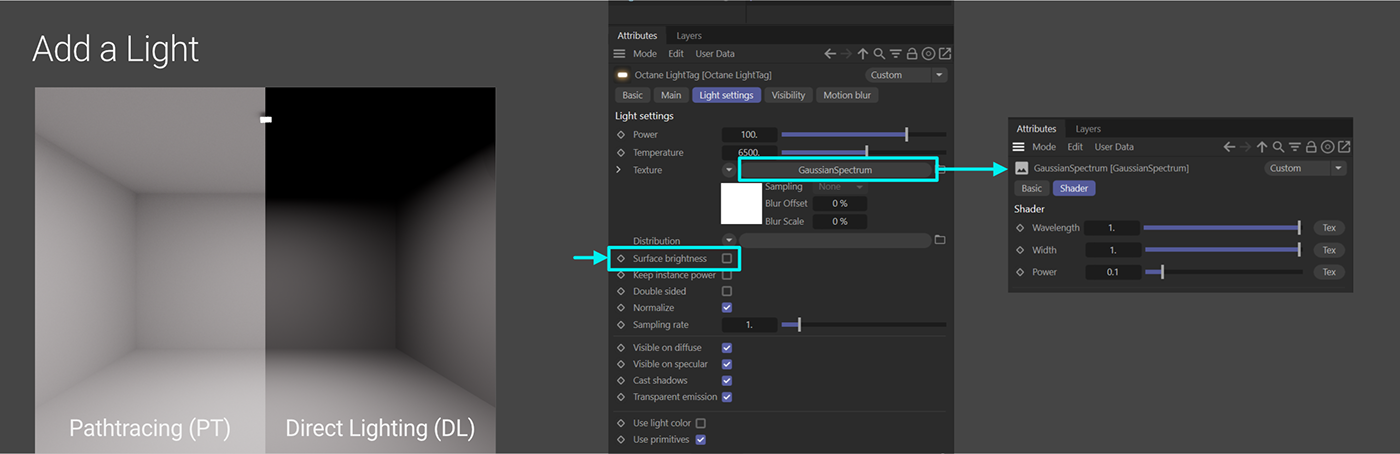
Let’s add an Octane Area Light into the scene, We’ll see this big square embedded in our floor facing away from us that’s blowing out the room. The default area light is 200cm to a side (as large as our basketball player), and stupidly bright for this interior.
Let’s start by making the light a reasonable size - say 10 cm x 10 cm. That’s in the Light Object’s attributes (not the Octane Light tag’s), in the Details tab. Now let’s get it into position. For now, we’re going to put it 295 cm up on Y so it’s standing 5cm off the ceiling, and then rotate it -90 degrees on R.P so it’s facing down.
If we render this, it’s now way too dark, even though the light’s Power (wattage) is 100. A 100 watt incandescent fixture should light up a room this size.
If we look in the Octane Tag’s attributes, we’ll see that Surface Brightness is on. This is useful for neon tubes and arbitrary abstract lights (especially ones that animate in size), but it’s pretty terrible for interior light fixtures where we want to simulate real-world counterparts. Let’s turn this off. Suddenly our room goes from way too dark to too bright again. This is because the efficiency of the light (controlled by the Texture field) is way too high for its Power. The default efficiency for an area light is ~17%. An incandescent bulb is usually 10% on a good day. To fix this, we’re going to put a Gaussian Spectrum node into the Texture field, set its Wavelength and Width to 1, and its Power to 0.1. We’re now simulating a 100 Watt incandescent light, and there should be a reasonable amount of light in the scene.
It’s close, but it still seems too bright. That’s because we’re standing in an enclosed box that’s painted entirely with the the default Octane material. This is a Diffuse material (no specular/metallic contribution) with ~85% Value, or kind of a very light flat gray. Even though there’s no specular or metallic properties, it’s still reflecting light because we’re using the Path Tracing (PT) kernel.
If we switched to Direct Lighting (DL), we’d see that the ceiling is now black because none of the rays from the area light are directly hitting it, and there’s no bounce light off the floor or walls because we’re using the DL kernel. There’s some falloff around the tops of the walls where the bulk of light rays can’t quite hit, and then the back corners are dark because they’re the furthest away from the fixture, and light loses more energy (intensity) as it travels a further distance.
If we go back to Path Tracing, everything brightens up because we’re now seeing secondary bounces off the walls and floor. This also takes longer to calculate and render.
Texturing the Room
Let’s have a quick look at the impact on the wall and floor color for total scene brightness.
To texture the walls and floors individually, we’ll have to make our cube editable by selecting it and hitting C. While we’re at it, let’s rename it to “Room” in the Object Manager.
Important: by default, the normals on geometry in C4D face outward. We’re inside a cube, so all the normals are actually facing the wrong way. We can fix this by going into polygons mode, selecting all the polygons for our room and hitting U~R to reverse the normals. Now everything’s orange, and all’s right in the world.
Temporary Textures

The real-world interior light simulation program Dialux assumes a 70% ceiling brightness, 50% wall brightness and 20% floor brightness by default (probably average values for interiors). Let’s try this.
Let’s make a new Universal Material and rename it “Walls”. We want the H/S/V to all be 0 (or 0/0/0 if we’re using Octane’s R/G/B color model), and then bring the Float value to 0.5. This will give us exactly 50% without any color model conversion. Let’s go ahead and apply it to our cube.
Now let’s duplicate this material twice, call one copy “Floor” and set the Float to 0.2, and the other “Ceiling” and set the Float to 0.7. While in Polygons mode, we can select the ceiling of our room and drop the Ceiling material on it, and then select the room’s floor and drop the Floor material on that. This will create selection tags and only apply the materials to those polygons. We can see the effects of the reflected light by altering the float value of the floor and keeping an eye on the ceiling - it makes a big difference, even if we go to 0.3 (30%) instead of 0.2 (20%).
Better Textures
Let’s get some better materials in here and see what happens.
Important: Complex architectural interiors can end up using a TON of textures. Textures can eat up a lot of VRAM - way more than we’d think, so we need to be really careful about the number of these we put in our scene, and - maybe even more importantly - the pixel dimensions and bit depth. There’s a whole guide on this here.
The Floor
If we go to AmbientCG, we’ll see a few options for floors. Let’s grab the 4K PNG zip file for Wood Floor 051. We’re only going to use the Diffuse, Roughness, and Normal maps. Displacement would add too much render time and isn’t worth it here. Let’s add these maps to a new Universal Material (making sure to do it in a way that uses ImageTexture nodes instead of C4D native bitmap nodes). The Normal and Roughness maps should be set to non-color data since they’re, well, not color data.
Important: Realistic materials do NOT have a Specular of 1, and this can cause problems with noise and fireflies. We do want this floor to be pretty shiny, and in lieu of a Specular map, we can just leave the H/S/V to 0/0/0, and the float of 0.9 (instead of 1) to avoid any extra fireflies.

Before we go any further, we want to look at how much VRAM this floor is using. The textures themselves amount to ~84 MB on disk, but when Octane decompresses them, they end up using 256 MB of VRAM (found in Live Viewer>Materials>Octane Texture Manager). This isn’t a big deal with any current GPU that can run Octane, but we need to remember that this this is a single, barebones 3-texture material we’re looking at. We can imagine very quickly running out of VRAM if we had, say, 30 materials with eight 4K or higher textures apiece, and only were running a 6GB card. There are strategies to cope with this in the texture optimization guide, but the easiest way is to just use smaller versions if we can (2K or even 1K), and use as few of the image textures as we can get away with if our scene was going to get complicated.
When we replace our floor selection material with the wood planks, we’ll notice that the scale seems off. When applied to our 16x20 floor, the wood planks are 24 cm wide (about 9.5 inches). With the default UVW mapping, the larger we make the room, the larger the image tiles are. We can change this behavior by adding a Projection node set to “Box” and piping that into all of the Projection inputs of the ImageTexture nodes. - now, rather than relying on the UVs and geometry, it uses the scene scale and a six-sided cubic projection, which is great for a flat surface like our floor or walls. So the floor planks look about right now at 7.75 cm wide (3 in), which we can measure using the super high tech method of dropping a cube into the scene and scaling it until the edges line up with the edges of a plank in the Live Viewer, and then using the Attribute Manager to see what that distance is.
Walls and Ceiling
We’re going to leave the walls and ceiling matte, but bring up the brightness a bit by changing the Walls texture to 0.65 Float and the Ceiling to 0.8 Float. Walls are usually textured, but we’re going to keep ours perfectly smooth so we can tell what’s noise vs. what’s intentional texture.
Back to Lighting
Materials are important, but most of the heavy lifting in this guide is going to be around Lights, so let’s get back to that.
It’s worth pointing out here that at 128 samples we’re getting ~14 seconds on a mobile 3080 (~400 OB), and it’s looking really clean. Not final quality, but plenty good enough for lookdev.

Currently we have a razor-thin panel light at the top center of our room that’s emitting light uniformly in every possible direction from one side of the light geometry. The rays travel a reasonable amount of distance before going extinct - enough to hit the walls and reflect around the room a little, but not enough so that they’re blocked and start causing render errors (a.k.a. noise and fireflies).
If we go into the Octane Light tag and check “double sided”, we’ll see a very different story. All of a sudden the scene is speckled with fireflies and it’s crazy noisy. This setting causes the geometry to emit light from both sides, meaning half of the rays are now shooting up a few cm or so before being blocked by the ceiling and causing a ton of render errors. We want to avoid this at all costs. Let’s set that back to single-sided.
It’s not just the ceiling we’re worried about either - let’s move the light panel back in Z to 275. A similar problem arises: Horrible noise and fireflies appear everywhere just by shifting a powerful light too close to another piece of geometry. What we want to do to avoid this is limit the direction the light rays are emitting from the source (more on this in the Lighting guide). The best way to achieve this is with an IES light.
Adding an IES Light
Let’s disable the Area Light and try some real world lights. We’re going to use lights from Arkoslight, because they have a beautiful minimalist aesthetic, they’re really good about giving us the information we need, and their site is easy to navigate and download resources from. The overhead light we’re after is the Sky 2 Dim Dali 4000k WT. We can use the Configurator at the bottom to see all the various lights in the Sky family and download the files. This light is a 15 W LED fixture with a color temperature of 4000K.
We need to hit the download button on the far right for this light, and choose Photometric Files, and then IES. Then we want the CAD 2D/3D category>OBJ>Low Res file. Given the option, we always want low res geometry - we can always subdivide it later if we need to, and no point dropping in several thousand extra polys.
In the Object Manager, let’s go to File>Merge Objects. For now, we’re just going to use the default settings and hit OK.
When we merge in the OBJ file, we’ll see that it actually scaled properly to our scene, and the anchor point is right at the top where it would connect to the ceiling, so that’s nice. We could double-check this by looking at the specs for the lamp on the site (300mm diameter) and dropping in a similar-sized cylinder in the scene (15cm radius) to make sure it’s about right. Let’s stick this on the ceiling by setting the P.Y to 300 cm.
The fixture is one single polygon mesh object called SKY, and it has two materials applied to two poly selection sets - one for the housing (Carcasa) and one for the emitting surface (Pantella). We could go through the process of converting the materials, but since the housing is basically a semigloss white, we can just build a new one real quick and then concentrate on the light material.
For the housing, let’s make a Universal Material, call it Semigloss White, take the Specular to 0.9 and increase the Roughness to 0.5. In the Material Manager, if we hold Alt (or Option) and drag Semigloss White over the CARCASA material, it will replace it, and now the whole fixture is white.
Emissive Material

Let’s make a new Universal Material and call it Arkoslight Sky Emissive.
Typically with emissive materials that are always on, we want to kill all the contribution for all the channels except Emission. We’re going to do this for now since it’ll help us troubleshoot some other issues, but we’ll revisit it later when it becomes a problem. Let’s set the Albedo to 0/0/0, Float 0, and the Specular to 0.
Next we want to head to the Emission channel and choose Blackbody Emission. We know from the site that this is a 15 W fixture, so we can put 15 in the Power. We also saw that the temperature is 4000 K, so we can put that in the Temperature field.
The Texture field should be a Gaussian Spectrum set to 1/1/1. Wavelength and Width of 1 will create a full-spectrum light. We’ll be using the Gaussian’s Power for dimming.
Finally, the all-important Distribution field. This needs to have an ImageTexture node in it. The ImageTexture’s File field is where the IES file that we downloaded goes (A195-02-X2_SKY_2_4000K.ies). Color space should be set to non-color data, and it needs a Projection set to Spherical. The Spherical Projection node needs its Position set to Normal Space (IES Lights) in case we want to rotate the fixture.
If we render the scene, we’ll see that something’s off - a third of the light is blacked out, and there are lots of fireflies in the scene. Time for some troubleshooting.
Troubleshooting
When part of the light is blacked out like this, it could be that the material isn’t set up properly, or it could be that C4D isn’t happy with the geometry.
We just set the material up from scratch, so we’re pretty sure that’s not the issue, but just in case, we can hide the light fixture geometry, put a C4D Disc object into the scene in about the same place as the light would be, make it 15cm in diameter, set its orientation to -Y so it’s facing down, apply the material to that, and realize that it’s doing a fine job of cleanly lighting up the scene (and more importantly it’s not blacked out). If we move it close to the wall, we can check its distribution, which looks right also.
So that’s not it.
It’s probably the fixture geometry then. Let’s delete the disc and bring the light fixture back. Most of these files we find on manufacturer sites were created in a CAD program which thinks in procedural surfaces, and exported to OBJ or FBX which describes the geometry in hard-coded points and polygons. These converted files can be messy when brought into a 3D DCC like Cinema.

One thing we’ll notice if we look at the light object in the Object Manager is that there’s a tag on it that we’re not typically used to seeing (two little up arrows coming from a horizontal line). This is a Normal tag which defines the normals of the polygons. This can get all kinds of screwy because CAD programs don’t treat normals the same way as Cinema. If we delete this, we’ll see that the blacked out portion is gone. Awesome. C4D will now rely on the Phong tag for shading the normals instead of the wonky normals tag.
Going forward, we can tell C4D to use a Phong tag instead of the normals tag when we’re importing the geometry file.
Ok, so the light itself looks right now, but we’re still seeing fireflies, which means some of the lights rays from the emitting polygons are being blocked by other polygons. If we were to select just the emitting portion of the geometry and pull it away from the housing, we’d see that it’s a cylinder that’s nested inside the housing. The edge walls of the light emitting portion are intersecting with the inner walls of the housing, and that’s causing our render errors.
We could probably fix this by modifying the geometry of the light object, but this would get kind of annoying have to do every time, and it might impact the look of the actual fixture. An easier way would be to exclude the light housing itself from the light-emitting portion. We can do this via Light Linking.
Light Linking
We’ve had the ability for a while to exclude objects from specific area lights using something called “Light Linking”, but the drawback used to be that it was an all-or-nothing situation with emissive materials - they all had to be on Light ID 1. Fortunately, in recent versions of Octane, we now have control over light linking for individual emissive materials, so we can exclude only our lamp geometry from only our Arkoslight Sky material. This is going to be the easiest way to deal with the noise situation for this light.

To do this, we need to assign our Arkoslight Sky material to a Light Pass ID that’s not 1 (since everything defaults to 1). This setting is in the Blackbody Emission attributes just below the Distribution field. Let’s set it to 2.
Now we need to put an Octane Object Tag (Object Manager>Tags>Extensions>c4doctane Tags>Octane Object Tag) on our light geometry. In the tag’s Object Layer tab, there’s an option for “Use light pass mark” (should be mask). If we enable this, we’ll see a bunch of checkboxes appear - these are all the light ID passes that Octane can use, and they’re all on by default. If we uncheck #2, this piece of geometry will now ignore lighting from the emissive material, and suddenly our scene cleans up without fireflies in 64 samples.
Disclaimer: This method is actually introducing some bias into the scene and takes a tiny bit of the realism away. In the real world, the light would cast a little bit of glow on the angled inner walls of the fixture. At this scale, it doesn’t matter as much as, say, not having fireflies in the scene, but if we were doing a closeup beauty shot of the lamp itself, we’d probably need to investigate other methods of keeping the fireflies under control instead of using light linking.
Adding more lights
Let’s go for a more evenly lit room and install 3 more overhead lights. We can do this pretty quickly by making a Cloner, setting it’s Y position value to 300 cm so it’s on the ceiling, and making it 2 x 1 x 2 clones. If we nest our Sky light under this, we now have four overhead lights illuminating the scene.
We’ll need to be careful when cloning light sources - there are issues in Octane with cloners and nested objects, especially lights and emissives. Right now we have a single piece of geometry with the emissive material on a polygon selection, so it won’t affect us here, but we’ll have to keep an eye out for potential issues with our other objects, especially if we want to nest emitting geometry or lights under the main light geometry.
Xpresso Dimmer Switches
This is optional, but it makes dialing in the look of the scene a lot easier as we add more lights. We’re using the Gaussian Spectrum’s power to control the dimming of the lights which is annoying to access since it’s buried a few levels deep in the Object Manager. We can make our own top-level dimmer switch controls so we can access all the lights in one panel with a little automatic Xpresso generation (no need to code, promise!).

Let’s make a new null called “Light Controls” - we can park this at the top of the Object Manager and we’ll know right away where our dimmers are. Next we’ll need a User Data tag (Object Manager>Tags>Programming Tags>User Data) - this will let us make our custom fields. With the User Data tag selected, let’s go into the Attributes Manager, in the User Data menu and choose Add User Data.
Here we want the name to be Overheads (which will automatically set the short name), the Interface to be Float Slider, the Unit to be Real, The step to be 0.01, the min to be 0 and the max to be 1. Let’s turn on Slider Min and Slider Max too. This will give us a slider that goes from 0 to 1 in 0.01 increments, just like the Power field in the Gaussian Spectrum. If we hit OK, we’ll see that field appear in the User Data section of the tag. Great.

To hook this up, all we have to do is right click the word “Overheads”, go to XPressions>Set Driver (this says “you are going to control something that I’ll define in a sec”), then go into the Arkoslight Sky Emission material, into Emission, into Blackbody Emission, into Gaussian Spectrum, and then right click the word “Power”, go to Xpressions>Set Driven (Absolute). This says “use the exact value from the driver I defined earlier”. This creates a new null called Expression that has the Xpresso tag already hooked up for us. See, no programming!
Now if we go back to the User Data tag, as we slide the slider around, it brings the lights up and down. Excellent.
White Balance
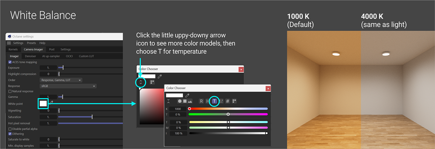
We added a warm wood floor and warm lights, so our scene is looking really yellowish now. In the real world, our eyes would eventually adjust to this and it would seem normal, but a camera (real or simulated) needs to be told which white balance value to target if we’re after a more neutral look.
The most accurate way to do this is to go into the Octane settings, into the Camera Imager tab, and change the color of the White Point. If we’re overriding the Camera Imager settings in the camera object itself, we’d have to do this in each camera’s settings as well.
If we click the little white color square, we’ll see a color chooser pop up. If we click the little uppy-downy arrow icon, it’ll give us more options for color models. The “T” (Temperature) model is what we’re after here. If we click that, we’ll notice a K field at the top - that’s Kelvin, same as our lights. All our lights are currently 4000K, so if we type 4000 into that field, the white balance of the camera MIGHT adjust for that temperature and our room might look neutral again.
Important: There’s a weird bug where in some builds of C4D and/or Octane, simply typing a value into the K field doesn’t do anything. If we click in the field after typing 4000, and then hit the up arrow so it goes to 4001, and then the down arrow so it goes back to 4000, it seems to wake it up and sets the temperature correctly. If not, we can grab the slider and move it left and right a little which should force it to update.
We may decide that we liked the warmer look (but not as warm as it was) and shift it to the right a bit, or we might decide that we’re after a cooler look and move it a bit to the left, but having that accurate starting point is really helpful. This can also be fixed in a post app, but it’s usually better to get the white balance in the camera right to make choosing material colors easier.
So now we’ve got a very fast-rendering interior without an HDRI or sunlight! Unfortunately it’s a very boring, fast-rendering interior. Let’s take a look at adding some more stuff in the scene and a few more lights.
Part II: Adding Some Stuff
Let’s get a sofa model in there for scale. C4D’s Asset Library has some good options, so let’s search for “sofa” and pick the Sofa Design 01 - 3 Seat and drop it in. This model is at real-world scale already, so we just need to position it against the back wall (P.Z = 290 cm). The sofa in its current state is about 800,000 polygons, which is just insane, so we need to do some surgery. First off, after a little digging, it turns out that the seams are 320,000 of those polygons. Not worth it, let’s delete the Seams object.
The sofa is also in a Subdivision Surface object which adds a ton of extra geometry - we don’t need that level of detail in our current view, so let’s click the green check next to the Subdivision Surface to turn it off. We’re still looking at 100K polygons which is too many, so let’s put the sofa in a Polygon Reduction object and hit C to make it editable. There, 18K total polys in the scene. Much better. If we need a super closeup of the couch later, we can bring in a higher res version of the model.
The leather material on it is going to take far more effort than it’s worth to convert, so we’re going to replace this with a basic light gray so we can focus on the lighting. Let’s duplicate our Semigloss White material, rename the copy Semigloss Gray, and set the Albedo’s Value to 70%, and apply it to the couch.
Next up we’re going to want a side table, so let’s search the Asset Library for “table”, and pick Bedside Table 10. This is only 20k polys, so no need to reduce it. The wood material will probably cause some problems and also isn’t worth converting, so let’s duplicate our Semigloss Gray, change the Albedo value to 50%, call it Semigloss Dark Gray, and holding Alt (or Option) drag the material itself over the Wood material in the Material Manager (not the floor) to replace it. We can also replace the White that came with the table with our Semigloss White using the same method. Let’s put that at P.X = 150 cm and P.Z = 250 cm. If we select the table, hit Shift-C, type “Instance” and choose it from the list, it will create an instance of the table for us. If we set the instance’s P.X to -150 cm, it’ll put it on the other side of the couch.

Revisiting the camera
The objects in the room now look sad and far away. We could move the camera closer, but the reason we made the angle so wide in the first place was to try to get as much in frame as possible. While 18-24mm is common for interiors since we can only step back so far without bumping into a wall, somewhere between 35-60 mm is actually ideal for showing objects the way our eyes see them, so if we have the space (which we do), we should definitely tighten up the focal length. Setting it to 35 mm in the Camera Object’s settings will frame up our scene better and have the added benefit of reducing some of the wide angle distortion. Nice!
Table Lamp
Next up let’s put a lamp on the table. Our friends at Arkoslight make a cool one called Yoru. Once again, let’s grab the low poly OBJ geometry and IES light texture from their site. We also want to make note of this being a 2.6 Watt 2700 K light. It’s battery-op, so we don’t have to worry about plugs which is handy. Let’s import the OBJ, but this time in the import options, set the Normals dropdown to Phong Tag to avoid the weirdness we had last time.
Let’s place this on a side table, so P.X = 150 cm, P.Y = 58.55 cm, P.Z = 250 cm. We’ll also want to rotate it so the button is out front - R.H = -90 degrees.
When we import the OBJ, we’ll see a bunch of polygon selections and materials - Bombilla (Spanish for Light Bulb) is the one we need. We can delete all the other materials and selection tags that came with it and put our semigloss white material on the lamp. This needs to go BEFORE (to the left of) the Bombilla selection tag to work properly.
Emissive Material
If we go into our User Data tag and dim our overheads to zero, the scene goes black, and we’ll be able to see what the lamp is doing once we apply the material.
To make the IES material for the Yoru, we can just duplicate our Arkoslight Sky Emission material, rename it Arkoslight Yoru Emission, swap out the IES file for the Yoru one in the File field, reduce the Light’s Power to 2.6, change the Temperature to 2700 K, and make sure the Gaussian Spectrum’s Power is back up to 1 to create the Emission material for this lamp. Let’s replace the light-emitting material with this one by going into the Material Manager, holding Alt (Option on Mac) and dragging the Arkoslight Yoru Emission material we just made on top of the Bombilla Material the light came with.
AI Light

What we’re looking at is a problem that’s plagued unbiased engines from the time they were conceived of. The only light source in the scene is now a small, dim, partially obscured Emissive material, and we can see from the amount of noise and fireflies that Octane is seriously unhappy about this development.
Fortunately, there’s a one-click solution that will help clean this up substantially. In the Octane Settings, in Kernels, there’s a checkbox for AI Light. When we turn that on, we’ll see a substantial reduction in noise and fireflies. They’re not all gone, but it’s SO much better.
Modifying the Sky Material
Now that we have the overheads turned off and another light source in the scene, we can immediately see a problem - the overheads look like black holes in the ceiling. When a real world light is off, we can still see the housing, so we’ll need to modify the material.
Right now our Albedo and Specular are both off - we want the Albedo to be 95% V (or 0.95 float), and the Specular to be 0.9. Now we can see the lights even though they’re off, and this won’t alter the look once we turn those lights back on. This is fine for full-spectrum lights, but could cause problems for colored ones - just something to keep in mind.
Exclusion

Back to the side table lamps - let’s see what happens if we try the exclude geometry from the light trick we used on the previous fixtures.
Since we duplicated the Sky light material, the Yoru emissive material should already be set to ID 2. To avoid excluding any geometry from the overhead lights, let’s set this to ID 3 instead (Emission > Blackbody > Light Pass ID = 3).
Now let’s grab the Octane Object tag from the Sky light geometry, duplicate that, and put it on the Yoru. In that tag we need to check 2, and uncheck 3. Now the lamp is being excluded from its own emission. That cleaned up the scene fairly well and got rid of most of the fireflies, but the lamp looks odd because it’s not illuminated. We didn’t really have this issue with the Sky light because so little of it was self-illuminated, but it sure looks weird here.
The reason it’s still noisy is that the table itself is a little too close the light - if we exclude that as well, we’ll see the scene once again clean up nicely at even 64 samples, but it looks even more wrong now. So we have a choice to make - do we go as clean as possible and fake the rest, or compromise and just exclude the lamp and deal with the noise from the table another way?
The reflected light from the lamp doesn’t really affect anything else in the scene, while the reflected light from the table definitely does (and would be harder to fake), so let’s just exclude the lamp for now and put a fake glow on that, and then deal with the noise separately.
Adding a Fake Glow to the Table Lamp
In order to keep the lamp excluded from its light source, we we’ll need to cheat here a little and add a second light to just illuminate the lamp. The theory here is to use the same Yoru IES light source, but dim it way back so it only splashes on the lamp itself. If the rays are weak enough, it shouldn’t add a lot more noise to the scene.

We have two options. We can either create a new piece of geometry, duplicate the material we have, and lower the power, or we can put in an Octane Area Light and set it up with the IES file. A disc won’t intersect with the lamp geometry if we open up an inner radius on it, but the Area Light is set to a Spectron Primitive by default which is a lot less noisy than an emissive material. Turns out after trying both that the Spectron light is the better option (less noisy).
Let’s head into the Live Viewer, under the Objects menu and choose IES Light. This will create an Area Light with a few handy presets. In the Light Object’s (not the tag’s) Details tab, we want to set the radius to 3.5 cm so it fits under our lamp nicely. If we nest it under the Arkoslight Yoru object, we can hit Alt-0 (zero) to zero out the coordinates relative to the light geometry. Now if we go into the Light’s coordinates tab, we can set the P.Y to 21.35 and the R.P to -90 and it should sit nicely near the top of the lamp aiming down.
The rest of the settings are in the Octane Light Tag on this light. Just like the material, we want Power to be 2.6, Temperature at 2700, Texture is Gaussian Spectrum set to 1/1/0.03 for now. We want the Gaussian Spectrum’s Power SUPER low so the light only brightens up the lamp itself and doesn’t splash everywhere and create excessive noise and fireflies.
Distribution already has an ImageTexture node in it because it’s an IES light, so we can dive into that (not replace it!) and load in our IES texture (A456-00-00_YORU_2700K_CRI90.ies) in the ImageTexture’s File field. Color Space needs to be set to non-color data, and the IES Light already comes with a spherical projection set properly, so no worries there.
If we go back up one level to the Light settings again, we want to make sure our Light pass ID is at 4 - this is how we’re going to make sure it only affects the lamp geometry. The other important thing is to go into the Visibility tab and turn off Camera, Shadow, and General visibility so the actual light object isn’t blocking anything and causing issues.
The last thing we want to do is exclude the table from this light, so let’s copy our Octane Object Tag to the table, and in the tag’s Object Layer tab, check 3 so it’s still seen by the Yoru’s main light and uncheck 4 so the fake glow doesn’t affect it.
So this definitely adds some more noise and a few more fireflies to the scene, but we’re still only at 128 samples, so we have some room to clean that up.
Duplicating the lamp
Here’s where the nested object issue would be a problem. If we made an Instance of the lamp, we’d have to constantly disable and re-enable it to get the glow to work right after we hooked up the xpresso. Rather than that, we just want to duplicate the lamp geometry (control-drag it down or ctl/cmd c, v), and then change the P.X of the main null to -150.
Adding controls to our panel
Let’s head back to the User Data tag on the Light Controls null, and under the User Data menu, choose Manage User Data. All we have to do here is take the Overheads entry on the left and Control-drag (Cmd-drag on Mac) it down a little to duplicate it twice to make two more sliders. Let’s name the first one Table Lamps in the Name Field, and the second one Table Lamps Glow. We can hit OK here now.
Just like before, we want to right-click “Table Lamps”, go to Xpressions and choose Set Driver, then go to the Arkoslight Yoru Emission material, in Emission, in Gaussian Spectrum, right-click the Power there (the Gaussian Spectrum’s Power, NOT the material’s overall Power), and choose Set Driven (Absolute).
We’ll also need to do that for the Glow and the IES Lights we set up (again, the Gaussian Spectrum’s Power is what we want to drive). Back in the User Data, let’s set the glow back to 0.03. Here’s the thing though… we’re controlling the main emission via the material, so it’ll control both lamps, but we’re controlling the glow Area Lights individually, so we’ll need the same slider to drive both lights.
Fortunately, we can have a one-to-many relationship here. We have Set Driver in memory already, so we can go over to the other copy of the light, into the Gaussian Spectrum, and right-click power here and choose “Set Driven - Absolute” as well. Now the same slider controls both glows.
This created three more nulls with Xpresso tags on them. We can move all the tags on our Light Controls null and delete the extra nulls to clean up the Object Manager.
Sampling Rate
Let’s see where we’re at with noise. If we head back to the User Data null, set the Overheads to 0.25, the Side Lamps to 0, and the Side Lamp Glow to 0, our scene cleans up relatively well at 128 samples. 128 is by no means final quality, and we haven’t even looked at denoising yet, but our overhead IES lights are doing a pretty respectable job considering the low samples.
If we turn on just the side lamp glow and se it to 0.03, we’ll see that it adds a tiny bit of noise, but nothing to worry about. When we set our side lamps to 1, that’s when we start to get some crackle and crunch. This was to be expected because of the light source’s proximity to the table.
Adding more samples would clean this up, but now that we have more lights, we can actually direct how much attention each light gets in the sampling process.
We do this via the Sampling Rate setting in the Blackbody attributes.

If we go into the Blackbody attributes for the Arkoslight Yoru Emission material, we can set the Sample rate to 4. This basically tells Octane to put 4x the effort into cleaning up rays from the lamps than the rest of the lights in the scene. Our overheads already resolved quickly, so they can afford to give up some attention.
We’re still only giving Octane a total 128 samples to work with, so the scene still has some noise which the AI Light system already did a great job of reducing, but it’s more evenly distributed now, and the problematic areas around the light lamp fixtures themselves look considerably better. This will help those areas even more when we denoise the scene.
Where We're At

The basics of our strategy are now pretty well set. We want to use as close to real-world lights, cameras, materials, and objects as we can. We want to limit geometry intersection as much as possible (especially self-intersection with lighting fixtures), and we want to reduce and even out the noise in the scene as much as we can by using AI light, and further guiding that with the Samping rate of individual lights.
If this was our final scene, we could get a very clean 512 sample denoised 1m:20s still, or a fast 128 sample denoised 20s animation frame that would hold up pretty well on the web.
Part III - Even More Stuff
Let’s make the room a little more interesting. Using our awesome modeling skills or our hacky Boole skills, we can add a few cutouts into that back wall. Either way, we’re going to need to make the final room editable again to make sure the normals are all facing the right way.
This file has the geometry (all taken from C4D’s Asset Library or built from scratch) that we’ll be using going forward. It does not include assets from Arkoslight or ambientcg.
Spotlights
First we’re going to add some lights into the hanging fixture on the right. We want these to be simple cones, so rather than hunting down an appropriate IES texture, let’s look at the Spotlight Distribution node. First thing we need is an Area Light. Let’s go into the Light Object’s Details tab and change the radius to 1.8. We know we want that radius because if we look at the housing where the light goes, we’ll see the inner radius of the tube is 1.9.
Next, we’ll want to change the Area Shape to Sphere. As of this writing, Sphere and Rectangle are the only two shapes that are converted to Octane Spectron Primitives, and will clean up faster than non-Spectron Primitives.
In the Octane Light Tag, we want the Power to be 2.5 Watts (they’re pretty tiny and shouldn’t put out a lot of light), Temperature is 2700 K, Texture is Gaussian Spectrum set to 1/1/1 for now. We want Surface Brightness off, and the Light pass ID set to 5 because we’ll very likely need to exclude it from the housing.
In the Distribution field, we’ll want a Spotlight Distribution (located in the c4doctane section of the down-arrow icon menu, or off to the left side if we’re using the node editor). If we click into the Spotlight Distribution, we can change the cone angle to 45 degrees to focus the light on the vases. We’ll also want to change the Orientation to Direction - object space. This will allow us to aim the spots if we want.

Let’s put this in place - the easiest way to do it is to nest the light object under the Tube in one of the hanging lights and then hit alt-0 to zero out the coordinates relative to the parent. The default object space direction of the distribution is straight up though, and we want it to go straight down, so let’s go into the Coordinates tab of the Light Object and rotate the light 180 degrees on R.P. We can copy this light two more times and nest each one under the other hanging light tubes, zeroing out the coordinates for each and then rotating 180 degrees.
Back to the Light Controls null in the User Data tag, we can Manage User Data again, duplicate one of our entries, call it Hanging Lights, and hit OK. Now we just need to right-click Hanging Lights, Xpressions>Set Driver, and then go into the Gaussian Spectrum Texture of each of our hanging lights, right-clicking the Power and choosing Xpressions>Set Driven (Absolute). Again, one controller can control three lights, which is cool. This makes three more Xpresso tags which we can move to the Light Controls null.
If we turn all our other lights off and set the Hanging Lights control to 0.25, we’ll see quite a bit of noise and fireflies at 128 samples. We’ll definitely want to put an Octane Object Tag on the Hanging Lights null and uncheck 5 in the Light Pass Mask section (after enabling light pass mark). That will exclude the lights from their housing and clean it up quite a bit. There are still some fireflies, but those should resolve with the denoiser and more samples.
Neon
Let’s light up the neon fixture in the left inset. There’s more info about neon textures in the Lighting and Emission guide, but basically we’re going to use a Texture Emission material for this and control the color with a Gaussian Spectrum. Getting the light color exactly right with a Gaussian Spectrum is tricky, but it ensures the best results for neon.

Our new material should be Universal, Albedo set to 0/0/0 and 0.95 in Float, Specular set to 0/0/0, 0.95 Float (just so when we turn the light off, it’ll look like a whitish color instead of a black void), Metallic at zero.
Emission should have a Texture Emission node hooked up to it. Most importantly here, since this a neon tube and can be set to any length or shape, we actually want Surface brightness to be ON so it doesn’t change intensity if we need to adjust the shape. Otherwise Power is at 15 (arbitrary since we’re not mimicking anything real-world - this can be boosted up or taken down as needed per-fixture) and Texture is Gaussian Spectrum.
What makes this different is that we’re controlling color with the Gaussian Spectrum, so we don’t want our settings to just be 1/1/1 (full spectrum light) like the others. To start, we don’t want anything too jarring in our mostly warm/neutral room, so we’re going to go with 1 for the Wavelength, 0.158 for the Width, and 1 for the Power. That will produce something similar to a warm-sh 2700K light. The Lighting and Emission guide goes into more detail about how to get particular colors, but it’s mostly a matter of playing with the Wavelength and Width.
Let’s go back to the User Data null in our Light Controls, duplicate another entry, rename it Neon Inset, hit OK. Once again we can do the Set Driver / Set Driven trick on the Power for the Gaussian Spectrum. The only thing to be aware of here is that the Gaussian Power also affects the color of the neon, so we may have to go back up a level and play with the Emission Power as well once we get the color dialed in.
Caustics
Let’s make a new area light, name it Vase Light, go into the light’s Details tab and change the Area Shape to Sphere in and the Outer Radius to 2.5 cm. In the Light Tag settings, let’s bring the Power all the way down to 1, the Temperature to 2700, Surface Brightness off, and add a Gaussian Spectrum into Texture, and set that to 1/1/0.25 (we want this to be pretty dim).
We’re going to nest this under the Glass Vase null and hit Alt-0 to zero out the coordinates, and then move it up 15 cm in Y so it’s in the middle of the vase geometry. Now let’s put the Basic Caustics Glass material (available in the download, or DIY Albedo & Specular=0/0/0, float=0, Transmission=1, Specular, IOR=1.512, Allow Caustics=ON) on the vase and hit render… aaaand the middle of the scene explodes into a mess of fireflies and noise. Path tracing is hit especially hard with caustics, but now we have a new trick up our sleeves - time to switch over to the new Photon Tracing Kernel!
If we open the render settings and under Kernels at the top, click where it says Path Tracing, we can pick Photon Tracing. Without doing anything else, if we change the samples to 128, we’ll see it takes a little longer, but suddenly that center part is now pretty much the cleanest part of the whole render.

The reason the material is called Caustics Glass is because in the IOR tab, Allow caustics is checked. This tells the kernel to consider anything with that material when calculating caustics - if it were unchecked, it’d spit out just as much noise as the Path Tracing kernel.
Once again, let’s make a new entry in our User Data tag for Vase Light, and use our Set Driver/Set Driven pattern to hook up the Gaussian Spectrum Power.
We can also swap out some of the other materials for the Basic Caustics Metals materials in the scene (Metallic=1, Albedo=50, 75, & 90, IOR: Allow caustics = ON). This will add some interest to the vases and elephants without adding more noise or fireflies. There are also a few other quick and dirty procedural materials in the download for the wallpaper and insets.
Finishing Up
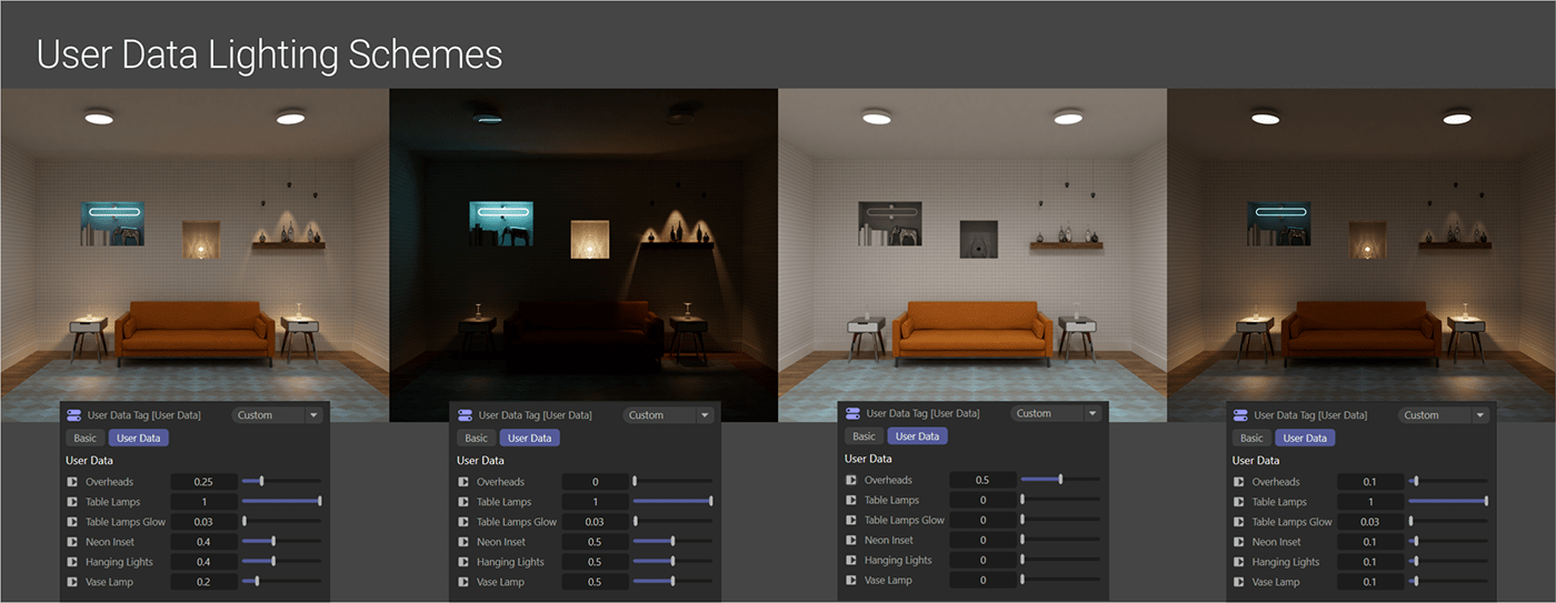
After bringing in a leather couch texture from AmbientCG and deciding on a neon and rug color, we can start playing around with our User Data tag to find a good balance of the lights in the room.
The total render time for this at 128 samples and the denoiser on an RTX 3080 Laptop GPU (~400 OB) is about one minute, ten seconds. 256 samples doubles the time, and marginally improves the quality, but two minutes for an interior with this kind of variety of lights AND caustics is not bad at all ☺
Author Notes
OG034 Interior Lighting: Stepthrough, version 1.0, Last modified July 2023.
This guide originally appeared on https://be.net/scottbenson and https://help.otoy.com/hc/en-us/articles/212549326-OctaneRender-for-CINEMA-4D-Cheatsheet
All rights reserved.
The written guide may be distributed freely and can be used for personal or professional training, but not modified or sold. The assets distributed within this guide are either generated specifically for this guide and released as cc0, or sourced from cc0 sites, so they may be used for any reason, personal or commercial.


